

PAK1865.40504
Clamping arm for swing clamps, Style D, For DK=40 steel, Hydraulic
Estimated delivery: On request
Simple clamping arms for swing clamp K1864. Thanks to the different shapes of clamping arms, various types of clamping can be realised. The fixing material is included with the swing clamps.
Material:
Steel.
Version:
burnished part.
Note:
The information on the clamping arm supports, as well as the effective clamping force as a function of the operating pressure, must be considered individually for each swing clamp.
The clamping force diagrams of the swing clamps are essential for dimensioning the clamping arms.
The operating pressure indicated must not be exceeded and must be adjusted if necessary.
The rotary movement of the clamping arms must take place without obstruction. Only when the rotation stroke of the swing clamps is completed can the workpiece be clamped.
The plungers must be set so that contact with the workpiece occurs only after the stroke of the rotary movement.
To ensure that no torque is transmitted to the piston rod, the clamping arms must be held during mounting.
Avoid interference with the rotation area. There is a risk of injury from crushing of the hands and other parts of the body.
Observe the safety instructions.
Mounting:
When fitting or removing the clamping arms, make sure that no torque is transmitted to the piston rod of the swing clamp. This can be avoided by applying force against the clamping arm when tightening or loosening the clamping screw.
1. In the case of a swing clamp with overload protection fitted, this must first be checked by turning the piston until the overload protection engages. A rotating clamp has three engagement points at a spacing of 120°.
2. The clamping arms are normally fitted without pressure. Once the clamping arm is positioned on the piston rod, the screw or nut can be tightened. If an exact clamping state of the clamping arm is required, the piston of the swing clamp must be retracted under pressure. The clamping arm can then be mounted in the desired position.
3. After the clamping arm has been secured, the clamping process of the swing clamp must be checked several times to ensure the clamping point and the clamping force.
4. After replacing a clamping arm, the torque of the clamping screw must be checked again after a few clamping cycles and, if necessary, the clamping screw must be retightened.
On request:
Other dimensions and shapes.
Accessories:
- Support pins K0307.
- Self-aligning ball supports K0302, K1164, K0287, K0288.
- Hexagonal-shaped grippers K0386.
Technical data:
- Max. operating pressure, form A and B: 200 bar.
- Max. operating pressure, form C: 500 bar.
- Max. operating pressure, form D: 300 bar.
| Material | Steel |
|---|---|
| Finishing | Burnished |
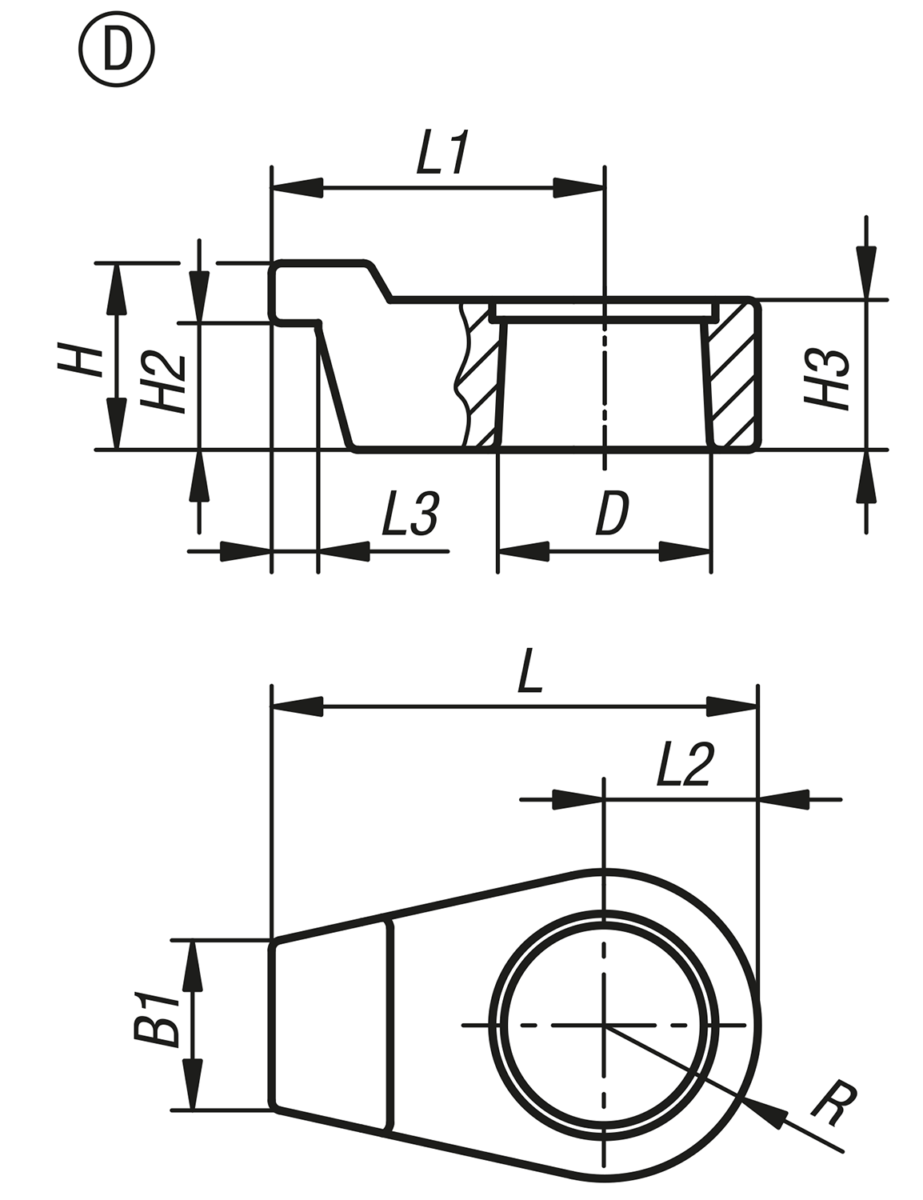
| H2 | 19 |
|---|---|
| L | 76 |
| H | 28 |
| L2 | 23 |
| B1 | 25 |
| D | 32 |
| L1 | 53 |
| D1 | 23 |
| L3 | 7 |
| Forma | D |
| Versão 2 | hidráulico |
| Versão 1 | para grampos giratórios |
| Denominação | Braço de fixação |
| Para o diâmetro do êmbolo | 40 |
| R | 23 |
| H3 | 22,5 |
Product Variations
| Model | Material | Finishing | H2 | L | H | L2 | B1 | D | L1 | D1 | L3 | Forma | Versão 2 | Versão 1 | Denominação | Para o diâmetro do êmbolo | R | H3 | Stock | Quantity | |
|---|---|---|---|---|---|---|---|---|---|---|---|---|---|---|---|---|---|---|---|---|---|
| PAK1865.25334 PAK1865.25334 | Steel | Burnished | 14,5 | 51,5 | 21 | 16 | 14 | 20 | 35,5 | 16 | 7 | D | hidráulico | para grampos giratórios | Braço de fixação | 25 | 16 | 15,5 | |||
| PAK1865.40504 PAK1865.40504 | Steel | Burnished | 19 | 76 | 28 | 23 | 25 | 32 | 53 | 23 | 7 | D | hidráulico | para grampos giratórios | Braço de fixação | 40 | 23 | 22,5 | |||

PAK1865.25334
Clamping arm for swing clamps, Style D, For DK=25 steel, Hydraulic
Material = Steel
Finishing = Burnished
H2 = 14,5
L = 51,5
H = 21
L2 = 16
B1 = 14
D = 20
L1 = 35,5
D1 = 16
L3 = 7
Forma = D
Versão 2 = hidráulico
Versão 1 = para grampos giratórios
Denominação = Braço de fixação
Para o diâmetro do êmbolo = 25
R = 16
H3 = 15,5

PAK1865.40504
Clamping arm for swing clamps, Style D, For DK=40 steel, Hydraulic
Material = Steel
Finishing = Burnished
H2 = 19
L = 76
H = 28
L2 = 23
B1 = 25
D = 32
L1 = 53
D1 = 23
L3 = 7
Forma = D
Versão 2 = hidráulico
Versão 1 = para grampos giratórios
Denominação = Braço de fixação
Para o diâmetro do êmbolo = 40
R = 23
H3 = 22,5