

PAK1385.138391
Unilock clamping module, ESM 138-C, Form B with anti-twist protection, Case-hardened steel hardened and polished
Estimated delivery: On request
Material:
Case-hardened steel.
Version:
Case-hardened and ground working surfaces.
Note:
UNILOCK clamping modules can be installed on work tables, in fixtures (plates, cubes, towers, etc.) with or without overhang in all positions. Pneumatic control of the clamping modules can be carried out individually or together.
In this way, a zero-point clamping system can be produced individually.
Thanks to the modular construction, the number and spacing of the clamping modules can be adapted to the clamping tasks. Set-up times are significantly reduced and machine running times are thus extended.
The high clamping forces are generated by the integrated spring assembly (the unit is clamped without pressure).
The release process is pneumatic.
Even in the event of a pressure drop or fluctuations in the compressed air supply, the full intake force is maintained.
All clamping modules have a turbo function included as standard. With a short air pulse at the "Turbo" air connection, the normal intake force, which is achieved by means of the springs, is once again significantly increased. Therefore, the clamping modules can also be used very well in heavy machining.
Use of the turbo function is recommended for maximum intake force.
With UNILOCK guide pins in combination with the clamping screws M10, M12, M16, the following holding forces are possible:
- Holding force (M10) 35.000 N
- Holding force (M12) 50.000 N
- Holding force (M16) 75.000 N
Holding force with cylinder head screw DIN EN ISO 4762-12.9.
The guide pins can only be fastened in conjunction with an exchange unit in the clamping module.
A uniform guide pin size in all clamping modules and compatibility with the 5-axis modular clamping system 80 ensure diverse combinations and application possibilities.
Advantages:
- Can be automated through various query options.
- Turbo function as standard.
- Repeatability ≤0,005 mm.
- Positioning by means of short cones.
- High intake forces.
- Setup time optimisation.
Scope of delivery:
1x clamping module.
1x O-ring Ø110x1.
3x O-ring Ø9x1,5 for media supply.
6x fixing screws.
6x cover caps for fixing screws.
Accessories:
Guide pin K0967.
Protective pin for clamping modules K1010.
Cover for clamping modules K1010.
Observe:
Recommended nominal hose size:
- Up to four clamping modules, nominal hose diameter of 6 mm.
- From five clamping modules, nominal hose diameter of 8 mm.
Operating principle:
The clamping modules can be connected via the connections on the base plate or the threaded connection directly on the clamping module.
To ensure the function of the low-wear sliding clamps, the upper piston chamber must be vented via the "Turbo" air connection.
This can be implemented through one of the four options:
1) Connection and use of the turbo function on the base plate next to the "Opening" connection. In this way, the clamping module can be clamped again with a short air pulse, if required. (Recommended)
2) Simple hole for air outlet on the base plate that is connected to the turbo connection. To cover the hole against dirt, a connection with a blocking function must not be used; a vent screw must be used instead.
3) In the third case, the piston chamber must be vented through a hole that is connected below the base plate via a transverse groove. The hole must face the turbo connection so that venting can take place.
4) In the case of lateral control of the clamping module, the vent screw must also be inserted at this point.
Technical data:
- Intake force with turbo of 25 kN.
- System pressure: 6 bar, lubricated air.
- Repeatability ≤0,005 mm.
- Temperature range 5 °C to 60 °C.
- Optional connection for cleaning air.
- The third air connection can be used open or closed as a query function for the low-wear sliding clamp.
Drawing note:
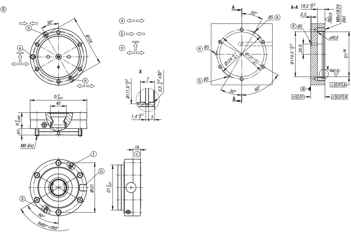
a) bottom connection without hose (open)
O-ring Ø9x1,5
b) bottom connection without hose (Turbo)
O-ring Ø9x1,5
c) centring edge
d) vent
e) bottom connection without hose (detection of locking pressure/positions of the sliding clamp)
O-ring Ø9x1,5, 2 bar, 15l/min
f) side connection G1/8 (actuation to open)
g) side connection G1/8 (Turbo)
h) anti-rotation protection Ø14 H7, depth 8 mm
The connections of the clamping modules are marked with arrow symbols on the outer diameter.
| Material | Case-hardened steel |
|---|---|
| Finishing | Hardened and polished |
| Forma | B |
|---|---|
| Versão 2 | ESM 138-C |
| Versão 1 | Unilock |
| Denominação | Módulo de fixação |
| P | 6 |
| H | 39 |
| H1 | 16,7 |
| Forças de admissão com turbo kN | 25 |
| D1 | 110 |
| Tipo de forma | com proteção contra torção |
| D | 138 |
Product Variations
| Model | Material | Finishing | Forma | Versão 2 | Versão 1 | Denominação | P | H | H1 | Forças de admissão com turbo kN | D1 | Tipo de forma | D | Stock | Quantity | |
|---|---|---|---|---|---|---|---|---|---|---|---|---|---|---|---|---|
| PAK1385.138391 PAK1385.138391 | Case-hardened steel | Hardened and polished | B | ESM 138-C | Unilock | Módulo de fixação | 6 | 39 | 16,7 | 25 | 110 | com proteção contra torção | 138 | |||

PAK1385.138391
Unilock clamping module, ESM 138-C, Form B with anti-twist protection, Case-hardened steel hardened and polished
Material = Case-hardened steel
Finishing = Hardened and polished
Forma = B
Versão 2 = ESM 138-C
Versão 1 = Unilock
Denominação = Módulo de fixação
P = 6
H = 39
H1 = 16,7
Forças de admissão com turbo kN = 25
D1 = 110
Tipo de forma = com proteção contra torção
D = 138